Are Upstream and Downstream O2 Sensors Interchangeable? How to Tell Them Apart

The short answer is no. This guide breaks down the exact mechanical and electrical differences between these two sensors. By reading on, you will gain master-tech diagnostic insights, learn a foolproof 4-step checklist to tell them apart instantly


Imagine you’ve finally tracked down that stubborn Check Engine Light to a faulty oxygen sensor. You head to your workbench, unbox the replacement, and suddenly panic sets in: the old sensor and the new one look almost completely identical. Can you just twist it into any open exhaust port and call it a day? Are upstream and downstream O2 sensors interchangeable? Let’s get right to the point.

Can Upstream and Downstream O2 Sensors Be Swapped?
No. In 99% of modern vehicles, upstream and downstream oxygen sensors cannot be mixed, swapped, or interchanged. While they belong to the exact same component family and might look like twins on your workbench, they serve fundamentally different functions in your engine management system. They send entirely different voltage signals to the engine control unit (ECU), operate on different software logic, and frequently feature distinct electrical designs.
Trying to force an upstream sensor into a downstream position (or the other way around) is a recipe for trouble. It will immediately confuse your vehicle’s computer, cause severe fuel miscalculations, compromise engine performance, and ensure your Check Engine Light stays illuminated permanently.
Why They Can't Mix: Different Roles, Different Tech
To appreciate why these parts aren’t interchangeable, we have to look at where they live and how they communicate with your car’s computer. The ECU doesn’t just read data blindly; it expects specific types of feedback depending on the sensor’s location within the exhaust system.
Most modern cars are equipped with at least two sensors per exhaust stream (a standard inline-four engine has two, while V6 or V8 engines typically have four, though the count and layout can vary by vehicle). Together, oxygen sensors play a critical role in modern vehicles by helping the ECU constantly adjust the fuel mixture to keep the engine at the ideal 14.7:1 air-fuel ratio—about 14.7 parts of air to 1 part of gasoline—for efficient combustion and lower emissions.
1. The Upstream Oxygen Sensor (Sensor 1): The Fuel Manager
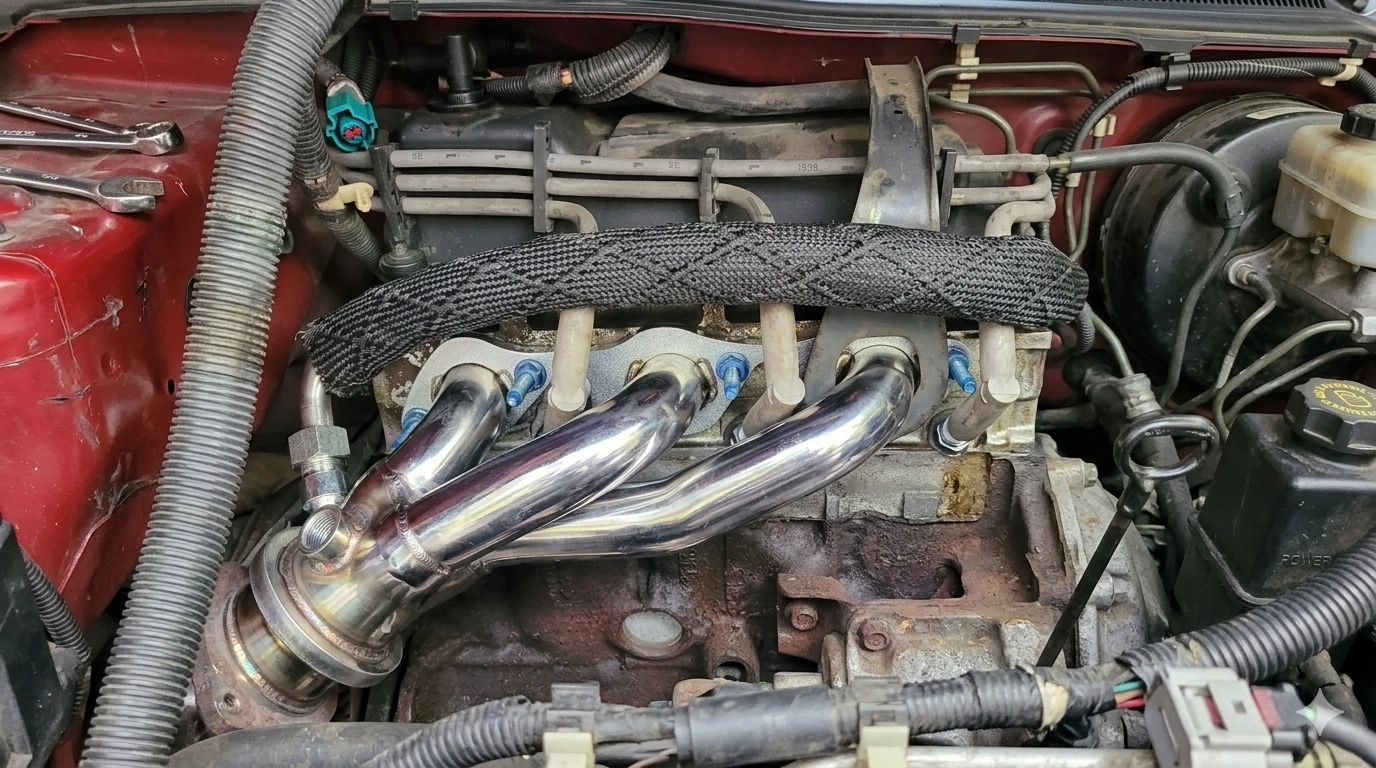
Located before the catalytic converter, right in the thick of it near the engine cylinder manifold, is the upstream oxygen sensor. Its primary function is measuring the raw oxygen concentration rushing straight out of the engine to provide accurate readings so the ECU can manage the mixture correctly.
-
The Mechanism: This sensor monitors the highly volatile oxygen content of raw exhaust using a platinum-coated ceramic element, generating voltage from the difference between oxygen in the exhaust gas and outside air. If the mixture is too lean (too much air, too little fuel), it generates a low voltage; if it’s rich (too much fuel), it triggers a high voltage.
-
The ECU Reaction: The ECU catches this rapidly fluctuating signal and uses it in a controlled closed-loop process to determine the right amount of fuel injector pulse width for better fuel economy and engine performance, millisecond by millisecond. When you first start your car, it runs in an open loop relying on fixed data until these heated sensors reach their proper operating temperature and take control.
-
Failure Symptoms: When this component suffers sensor failures, your engine loses its guiding eyes. You will immediately experience a sharp drop in fuel economy, a rough idle, and poor overall power. It can also cause hesitation or acceleration struggle, along with a check engine light and unusual exhaust odor or smoke. This typically triggers critical trouble codes like P0132 / P0134 (Circuit/Activity issues) or P0171 / P0172 (Fuel Trim Lean/Rich issues).

2. The Downstream Oxygen Sensor (Sensor 2): The Catalytic Converter Emissions Guardian
Mounted further down the line, right after the catalytic converter, the downstream sensors have a completely different objective from upstream units: the key difference is that they mainly verify catalyst performance rather than control fueling.
-
The Mechanism: Instead of measuring raw combustion, it samples the exhaust after it has been scrubbed of harmful pollutants like carbon monoxide, hydrocarbons, and nitrogen oxides.
-
The ECU Reaction: If your catalytic converter is working perfectly, the downstream sensor should produce a remarkably flat, steady, and stable voltage output. It tells the ECU that the converter is doing its job. Because its goal is environmental monitoring, it does not actively alter the primary air-fuel calculations under normal engine load.
-
Failure Symptoms: If the downstream readings start fluctuating wildly like an upstream sensor, the ECU knows the catalyst is dead, triggering the notorious P0420 catalyst efficiency code. If the ECU can detect a faulty downstream sensor or a related circuit issue, it may also set a trouble code, but that does not always prove the sensor itself is bad. If the downstream sensor’s internal heater circuit or wiring undergoes corrosion or fails, it throws specific electronics codes like P0037, P0138, or P2096.
What Happens If You Mix Upstream and Downstream Oxygen Sensors
Inside these components is a ceramic element that becomes highly sensitive to oxygen differentials when heated. Modern units are heated sensors, meaning they have an internal heater circuit that brings them up to temperature quickly.
Even if the threads match, interchanging them causes immediate system failures:
-
Signal Confusion: The ECU expects a dynamic, fluctuating signal from the upstream position and a flat signal from the downstream. If you swap them, the computer will interpret the steady downstream reading as a frozen, failing oxygen sensor upstream.
-
Incorrect Fuel Management: To compensate for what it thinks is a bad mixture, the ECU will wildly adjust the fuel delivery. This leads to a severe drop in fuel efficiency, a rough idle, and poor engine performance.
-
Catalytic Damage: Running a mismatched sensor can cause the engine to dump excess fuel into the exhaust system, leading to unburnt fuel igniting inside the catalytic converter, causing catastrophic melting and failure.
How to Tell Upstream and Downstream O2 Sensors Apart
If you have both sensors sitting on your workbench, you can easily differentiate them using this 5-point checklist:
1. Wire Length Matters
Because the upstream sensor sits high up on the exhaust manifold close to the engine bay, its wiring harness is usually relatively short. Downstream sensors sit far down under the floorboards, meaning they frequently require much longer pigtail wires to reach the vehicle's main electrical harness.
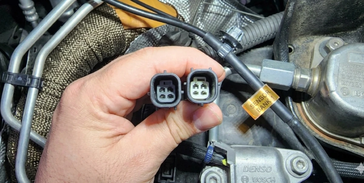
2. Inspect the Harness Connector (Keying)
Look closely at the plastic clips inside the electrical plugs. Car manufacturers intentionally design them with unique indexing slots (grooves), and the keyed connector design helps each sensor connect only to the correct harness location. Some sensor designs also use the metal case as a ground path, so the correct connector and wiring arrangement matter.
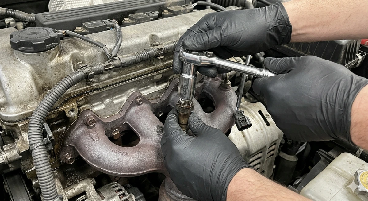
3. Analyze the Protective Tip
-
Upstream (Sensor 1): Often features a robust shroud with large, wide slots to handle intense thermal shock and sample rapid, raw exhaust pulses.
-
Downstream (Sensor 2): Frequently features a simpler design with tiny pilot holes, as the air it samples has already been filtered of heavy particulates by the catalytic converter.
4. Wideband vs. Narrowband Tech
Many modern vehicles utilize an advanced Wideband Air-Fuel Ratio Sensor for the upstream position to get precise readings, while keeping a cheaper, traditional Narrowband Sensor downstream—for example, an upstream wideband unit is not interchangeable with a downstream narrowband unit even if the threads look the same. They speak entirely different electrical languages, and their output characteristics are not proportional in the same way, so the ECU expects different signal behavior and cross-compatibility is impossible.
5. Part Numbers:
The most foolproof way in the automotive industry is to look at the stamped part number on the metal body of the sensor. Whenever you are in doubt, look for the stamped laser-etched numbers on the metal hex body of the sensor. Pop those numbers into a trusted OEM or auto parts database to confirm its designated placement.

Comparison at a Glance
|
Feature |
Upstream Sensor (Sensor 1) |
Downstream Sensor (Sensor 2) |
|
Physical Placement |
Before the Catalytic Converter |
After the Catalytic Converter |
|
Primary Mission |
Real-time Air/Fuel Adjustments |
Catalyst Efficiency Monitoring |
|
Pigtail Wire Length |
Typically Shorter |
Typically Longer |
|
Core Technology |
Often Wideband (A/F Ratio) |
Almost Exclusively Narrowband |
|
Drivability Impact |
High (Misfires, stalling, bad MPG) |
Low (Mainly emissions failure) |
|
Signal Behavior |
Rapidly fluctuating between 0.1V - 0.9V |
Typically around 0.45V - 0.7V |
Summary
Mastering your vehicle's exhaust components is the secret to unlocking optimal engine efficiency. For a complete deep dive into keeping this loop healthy, bookmark The Ultimate Guide to O2 Sensors: Boosting Engine Performance and Efficiency.
If a replacement is unavoidable, budgeting ahead is key. Read our expert breakdown on How Much Does It Cost to Replace the Oxygen Sensor? to ensure you get a fair price at the local shop, or buy the correct OEM part numbers for your DIY garage. Keep your sensors separated, double-check your plugs, and your engine will thank you with smooth performance for miles to come!


